
A smarter way to Design & Build
Let Cadnetics be the extension of your team. Get the reliable, on-demand support and cutting-edge technology you need to stay under budget and ahead of schedule.
Our core Services
Reality Capture
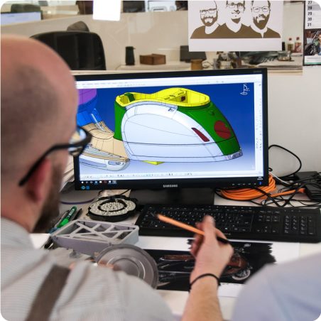
Design Support
Virtual Construction
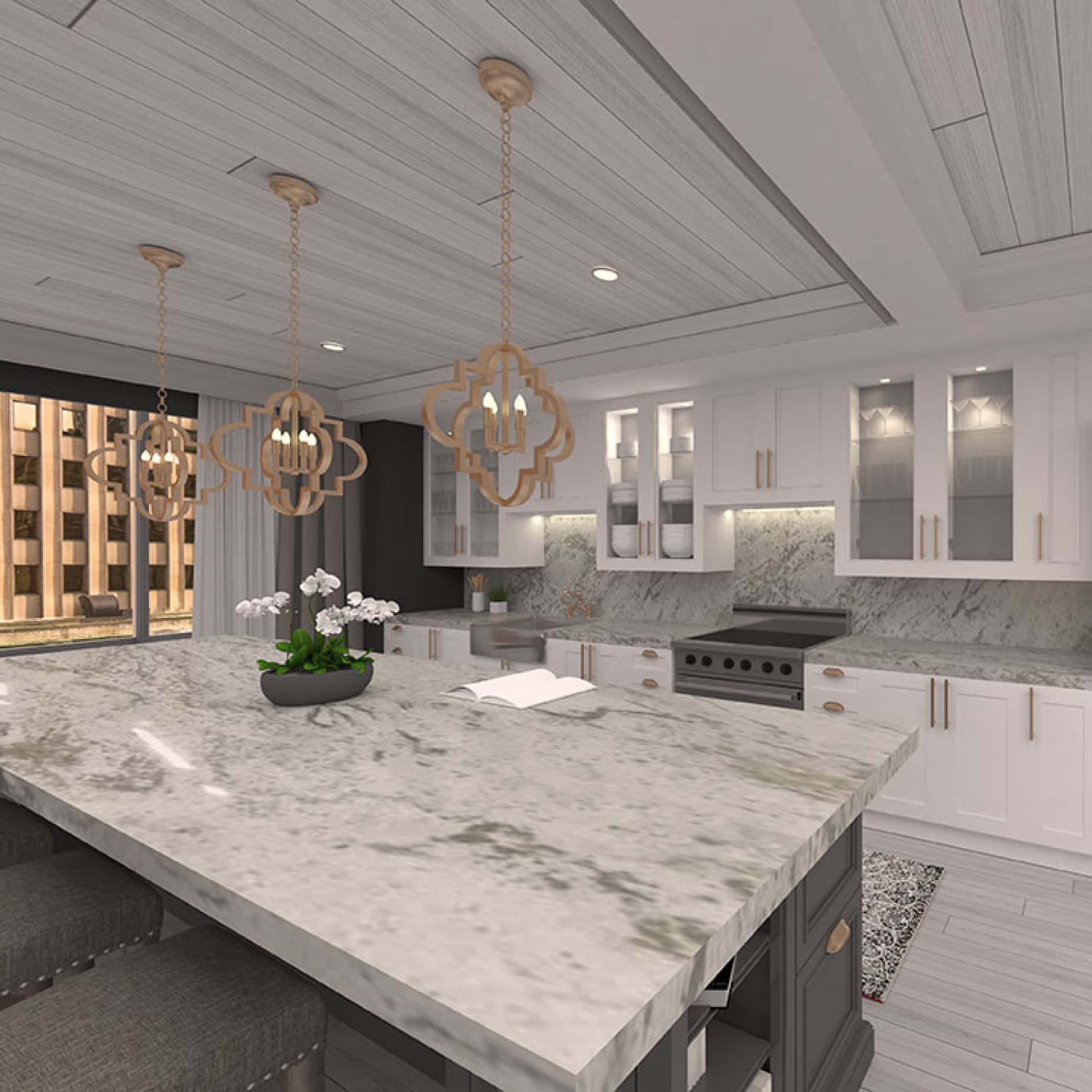
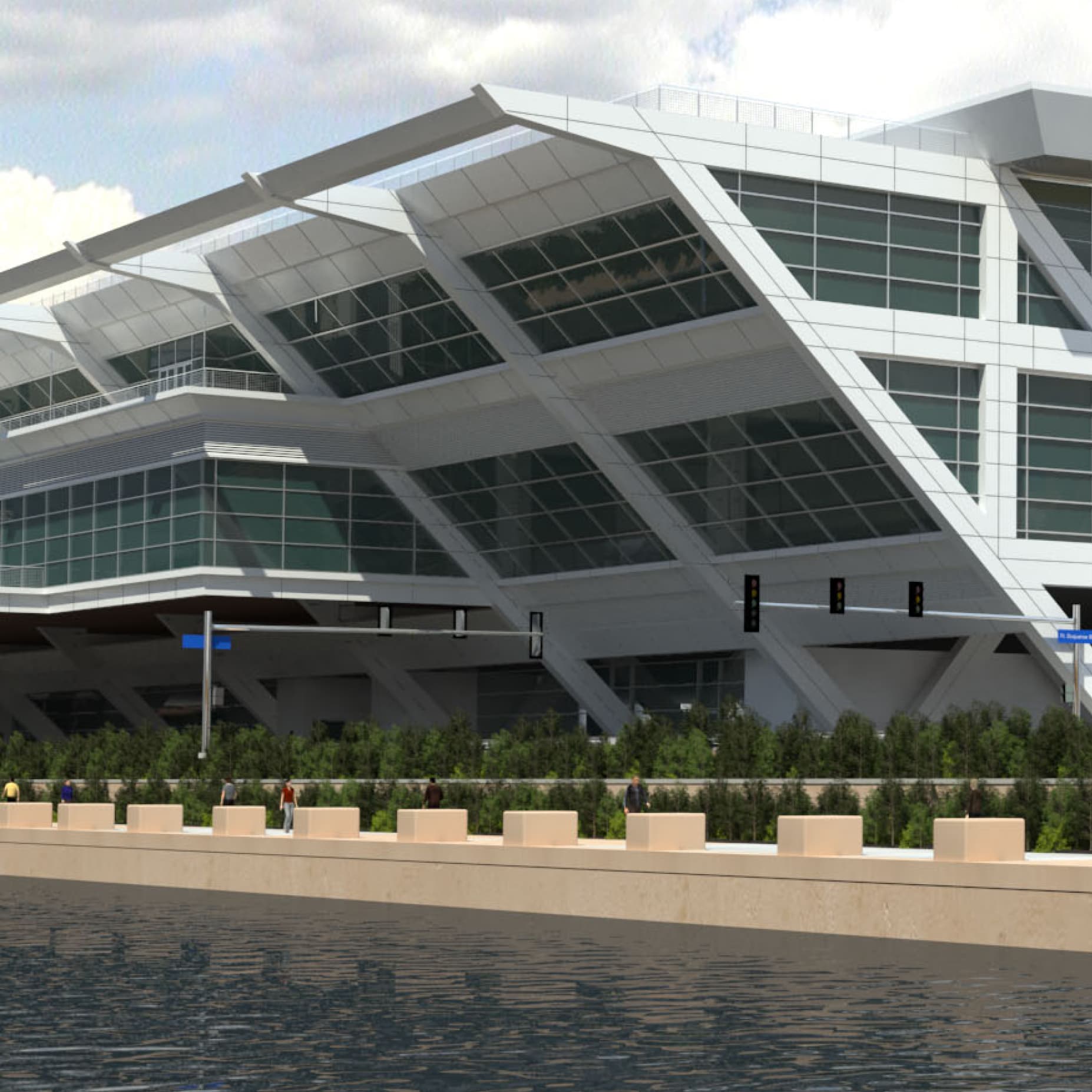
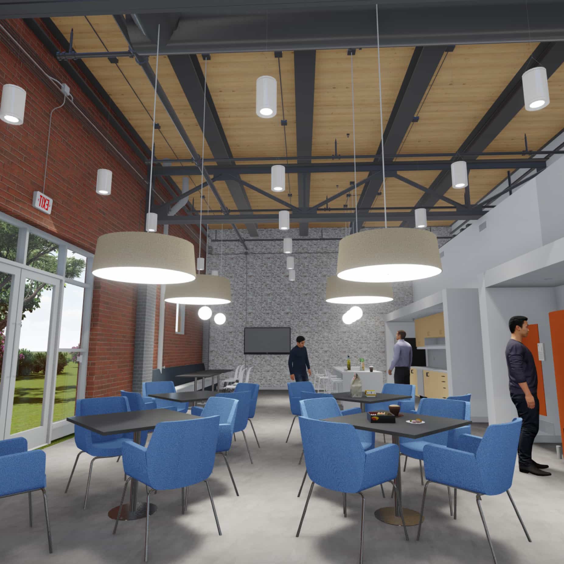
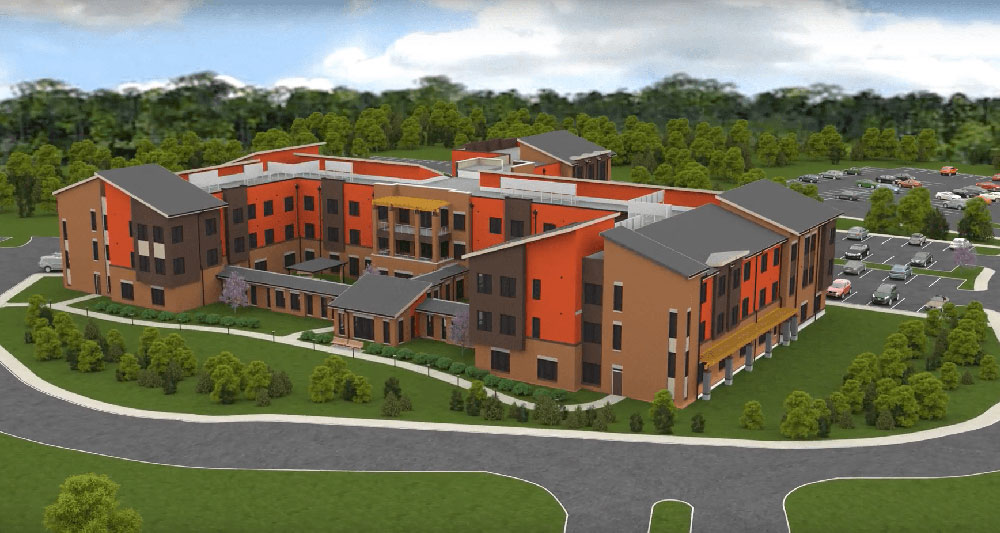
Visualization
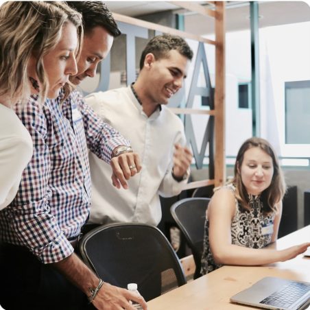
A seamless extension of your team
Complete solution
With our comprehensive service offerings, there’s no need to patchwork together multiple vendors to get the job done. We offer a complete, all-in-one solution that can be executed seamlessly from start to finish.
Industry-leading technology
Get access to the latest technology and skills without needing to invest in expensive equipment or specialized talent in-house. With our scalable solutions, pay for only what you need, and nothing more.
Flexible workflows
With our adaptable solutions, we fill the gaps in your projects and simplify your life. We offer on-demand support that fits seamlessly into YOUR workflow, not ours.
Reliable support
We understand how stressful tight deadlines can be and how much pressure you’re under, because we’ve lived it. We’ll go above and beyond to get your project done on time and on budget, period.
A few of our Happy clients


Expertise you can depend on
8000+
Successful projects completed
2000+
Happy clients served
30
Years in business
Pittsburgh roots. Nationwide impact.
We are proud to be forged in the "Steel City," the backbone of the building and construction industry in America. It is a hub for entrepreneurship, technology, ingenuity, and industrial force. As we have expanded our operations nationwide, we continue to hold these values close to our hearts.
-
[Cadnetics] did a great job, listened, and quickly reacted to every issue, concern, and modification that was asked... [they] took time to explain the next step to move forward. The entire process was precise and efficient, and very professional. The drafts/floor plans are exactly what I was looking for and the color 3d rendering is ideally my vision. Now I hope the appraisal helps me see through my business model. Thank you and the staff, for getting me one step closer to my vision and goal... I intend to use Cadnetics in any future projects. Jen, Tom, Billie, and Jim [have] all have been true professionals.
Channie Hill
-
Cadnetics is like the juice of our stew. They hold us together. When we expand or get into a tight situation, we put up the Bat signal and Cadnetics has answered that for 25 years. Cadnetics drafters are just amazing.
Dan Rothschild
President, Rothschild Doyno Collaborative
-
I just wanted to say thank you for the time and effort you put into the animation. I think we created something really unique and simple to digest. It was very well-received during the presentation, and contributed to our successful award of the project!
Chris Voros
Synder Langston
-
The presentation went extremely good. The customers were really quite impressed. The visualization really helped us tell our story and showed the customer we know the project inside and out. Thanks for all your work, it appears it will pay off.
Doug Huebner
Schindler
-
Because of our relationship with Cadnetics, we can provide a higher level of service and be more cost-effective internally and externally. We try to surround ourselves with the best people we can possibly find. We have had a long relationship with Cadnetics because of who they are which goes beyond what they do.
Jim Ferry
President, Ferry Electric Company
-
Cadnetics went above our expectations. It was a difficult job and their commitment made it happen. They noted every detail.
Perry Roofner
Vice President for Facilities, Robert Morris University
-
A big thanks to Cadnetics for jumping in and producing an as-built drawing for my new renovation project, saving me hours of time and effort. The drawing produced was exactly what was needed, well-executed, and delivered on time!
Van Auken Miller
Principal, Van Auken Miller Architects
-
Cadnetics has been extremely responsive to the needs of both our firm and our clients...Cadnetics is an extension of our office.
Ken Doyno
President, Rothschild Doyno Collaborative
-

Cadnetics has always responded with excellent quality, accuracy and timely delivery. We value your consistent performance as a reliable asset to our firm.
Arthur R. Ruprecht
Principal, RSH Architects
-

Cadnetics has been a fabulous resource for us over the years.... With Cadnetics I found that I could sit in my office, mark up drawings for 2 weeks, have a stack of drawings, and they would turn them around with 4 or 5 people working on them. It was much faster than if I had went through the troubling of hiring a person to do it in house.
Tom Carlins
Owner, Carlins Consulting
Select works we're proud of

Connected with the AEC Industry


Traditional Work Ethic. Modern Execution. Since 1993.
We're shaping the future of AEC. Will you join us?
Keep up with Cadnetics news


Ready to Get to work?
Let Cadnetics be the extension of your team. Get the reliable, on-demand support and cutting-edge technology you need to stay under budget and ahead of schedule.